Gate design is a key part in plastic injection molding process since it will have a direct impact on the occurrence of the undesirable product surface defects such as weld lines and air traps. In order to get the best results, the gate design is changed quite frequently during the simulation process; therefore, enhancing the efficiency of  gate position changes can save a great deal of effort and time spent in the simulation analysis. To help users speed up this product and mold design process, Moldex3D provides a useful gate optimization tool, Gate Wizard, which allows users to automatically create 9 types of gates, including an edge gate, a fan gate, a tunnel gate and a cashew gate. Furthermore, the newly-enhanced Moldex3D Gate Wizard provides an intelligent and intuitive interface, Gate Attributes, that increases the efficiency of gate optimization. Moldex3D users can now utilize Gate Attributes to adjust gate locations with more freedom The new enhanced features will be introduced below. If the runner system is already well designed, users can click the point at the end of the runner, and set it as the starting point of the gate. Then Moldex3D will automatically find the projected point on the product surface extending in the same direction as the runner from the end of the runner point, and set it as the end of the gate. The complete gate will be created accordingly. Take a cashew gate as an example, when a runner system has already been created (Fig. 1), and users can utilize Gate Wizard to click the point at the end of the runner to add a gate. If the “Locate at side of part†item is checked, Moldex3D will create a gate on the projected point on the product surface extending in the same direction as the runner from the end of the runner point (Fig. 2). If “Locate at side of part†is not checked, the cashew gate will be located on the point on the product surface along the melt direction parallel to the parting surface (Fig. 3). After setting the gates, users can further fine-tune the gate locations in the Gate Attributes interface. In short, as Moldex3D’s pre-processing interface makes the gate design changes more efficient and accurate, users can attain accurate simulation results with ease and effectively apply them in the actual injection molding product development. Surface quenching, CNC quenching equipment, heat treatment, high-frequency quenching machine, heating system, quenching machine tool Ningbo Dedao Electronic Technology Co., Ltd , https://www.nbdedao.comAdd gates at the end of the runner
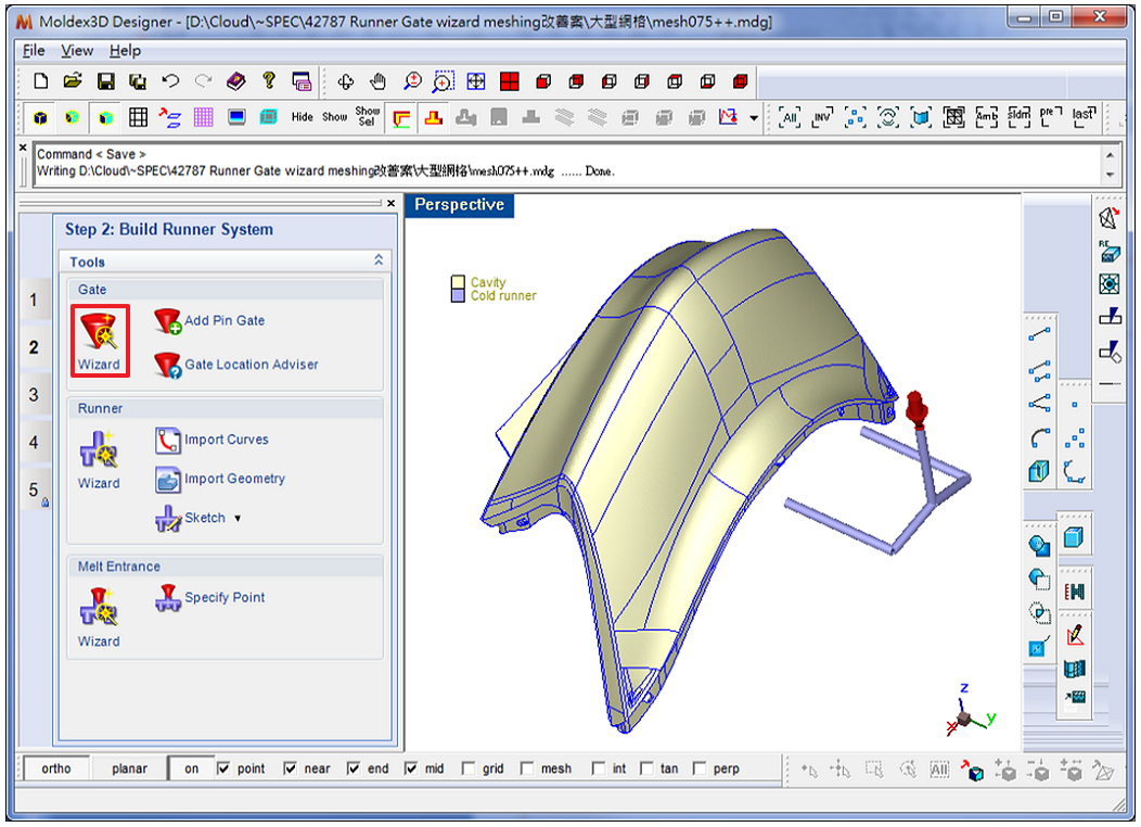 Fig. 1 Â A runner system has been created
Fig. 1  A runner system has been created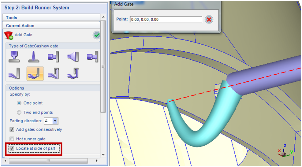 Fig. 2  Check “Locate at side of partâ€, and the gate will be created on the projected point on the product surface extending in the same direction as the runner from the end of the runner point
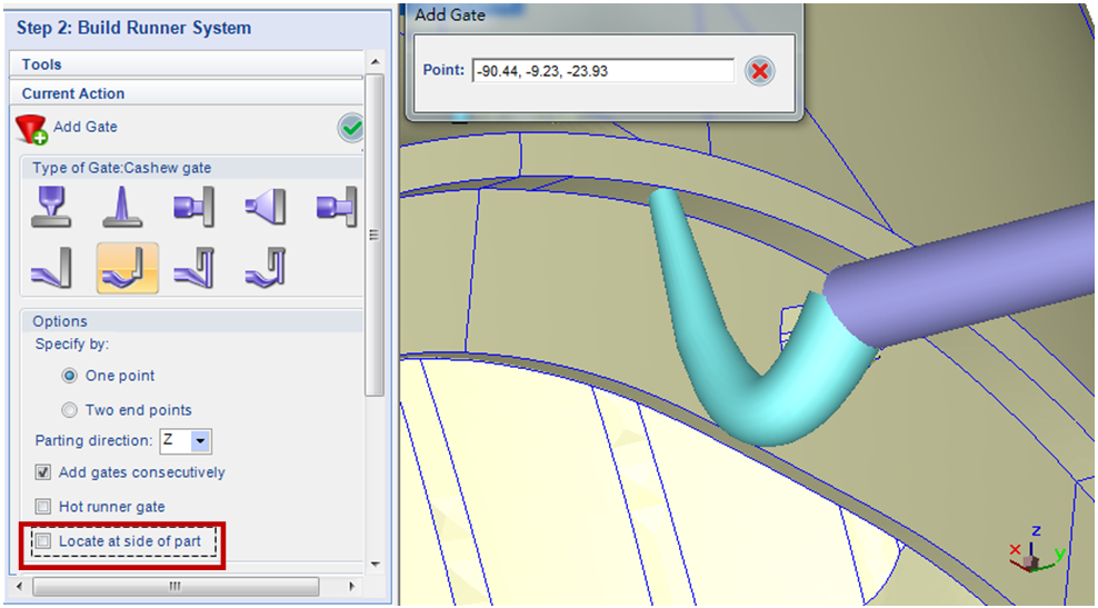 Fig. 3  If “Locate at side of part†is not checked, the gate will be located on the point on the product surface along the melt direction parallel to the parting surface
Interactive interface enabling gate location modifications
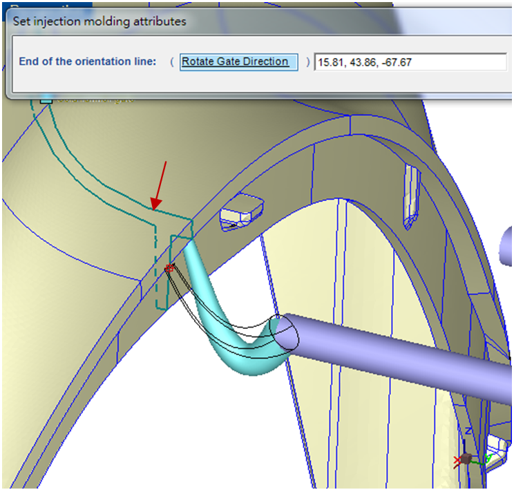 Fig. 4 Â Moldex3D is able to display cross-section lines (as the arrow shows) for users to adjust gate locations
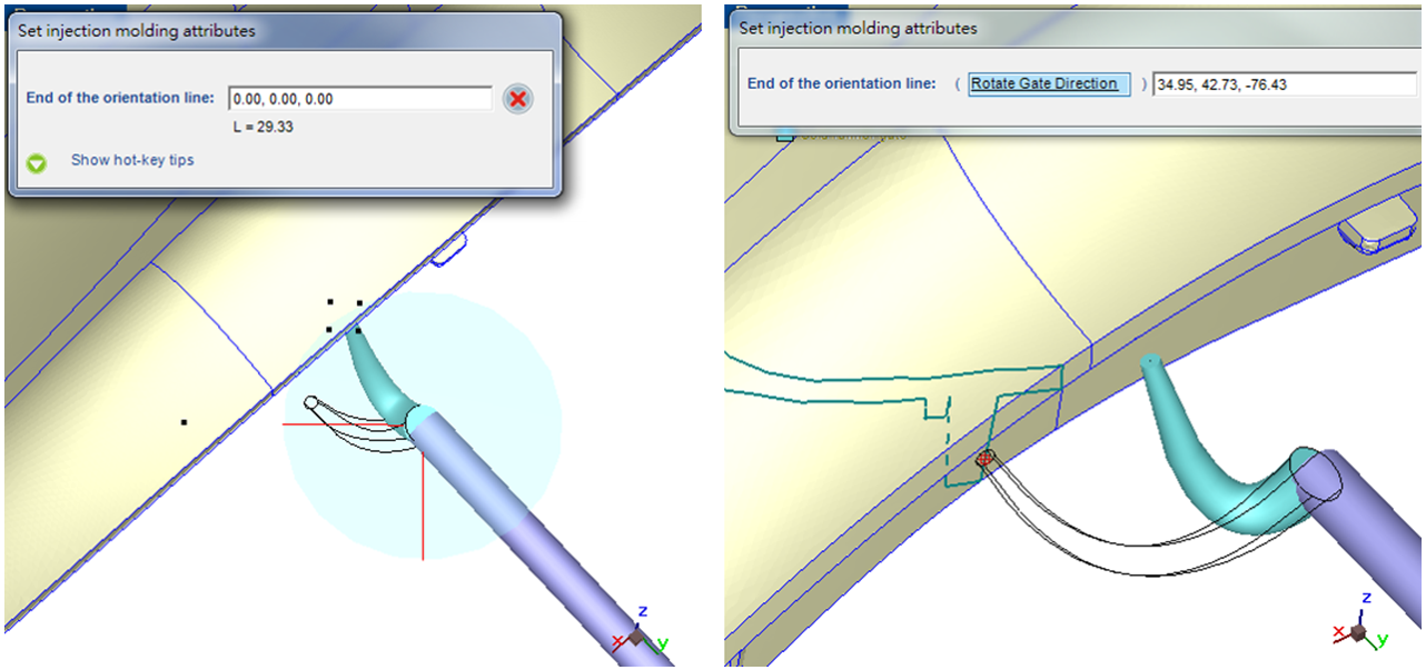 Fig. 5 Â After modifying the melt direction (left), users can adjust the gate location by observing the cross-section lines (right)Â
 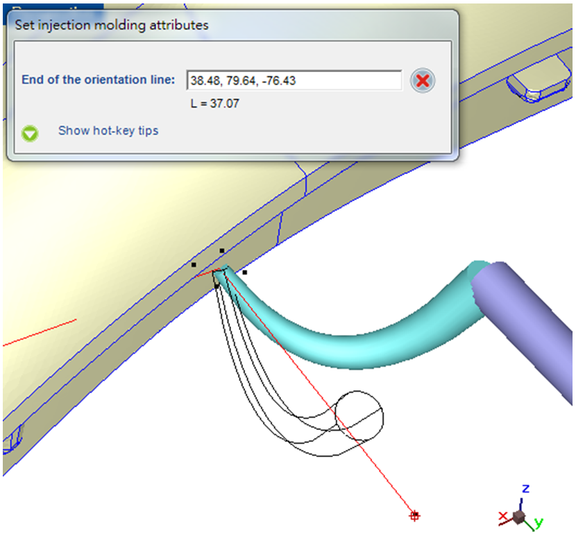 Fig. 6 Â Adjust the melt direction while the gate location is fixed
The CNC quenching system is a highly automated heat treatment equipment that utilizes computer numerical control (CNC) technology to accurately manage the temperature, time, and cooling rate during the quenching process, in order to change the microstructure of metal materials and enhance their hardness, wear resistance, and fatigue resistance. This system is widely used in fields such as mechanical manufacturing, automotive, aviation, and tool steel, and is crucial for improving product performance.
working principle
Numerical control quenching systems usually use induction heating or bath quenching for heating. Induction heating generates eddy currents through electromagnetic induction, rapidly heating metal workpieces above the critical temperature, and then immediately immersing them in quenching media (such as oil, water, or salt solution) for rapid cooling. Bath quenching is the process of preheating the workpiece to a certain temperature and then immersing it in a low-temperature medium for hardening.
system composition
Heating unit: induction coil or heating bath.
Cooling unit: quenching medium and circulating pumping system.
Numerical Control System: Control parameters such as heating temperature and cooling rate.
Workpiece loading and transport mechanism: Ensure precise positioning and movement of the workpiece.
Security protection: monitoring and emergency shutdown mechanism.
Key advantages
Precise control: Setting the quenching path and parameters through software programming, with good repeatability.
Improving quality: uniform hardening, reducing the risk of deformation and cracking.
Energy saving and efficient: fast heating and cooling, saving energy.
Flexible production: adaptable to different specifications and batch sizes.
Automated operations: reduce manual intervention and improve productivity.
Application Cases
Automotive components: wear-resistant parts such as gears, crankshafts, connecting rods, etc.
Aerospace: hardening of high-temperature alloys and lightweight alloys.
Tool manufacturing: cutting tools, mold steel.
Medical equipment: Enhanced treatment of surgical instruments.
Military equipment: firearm components, armor materials.
Technology Trends
With the development of intelligent manufacturing, CNC quenching systems are integrating more advanced technologies, such as machine learning algorithms to optimize quenching processes, sensors to monitor material properties in real-time, and personalized customization. At the same time, we will develop efficient cooling media and improve quenching trajectory planning to further enhance quenching quality and reduce costs. In the future, highly integrated one-stop quenching production lines will become the mainstream of the industry, bringing revolutionary changes to metal processing.