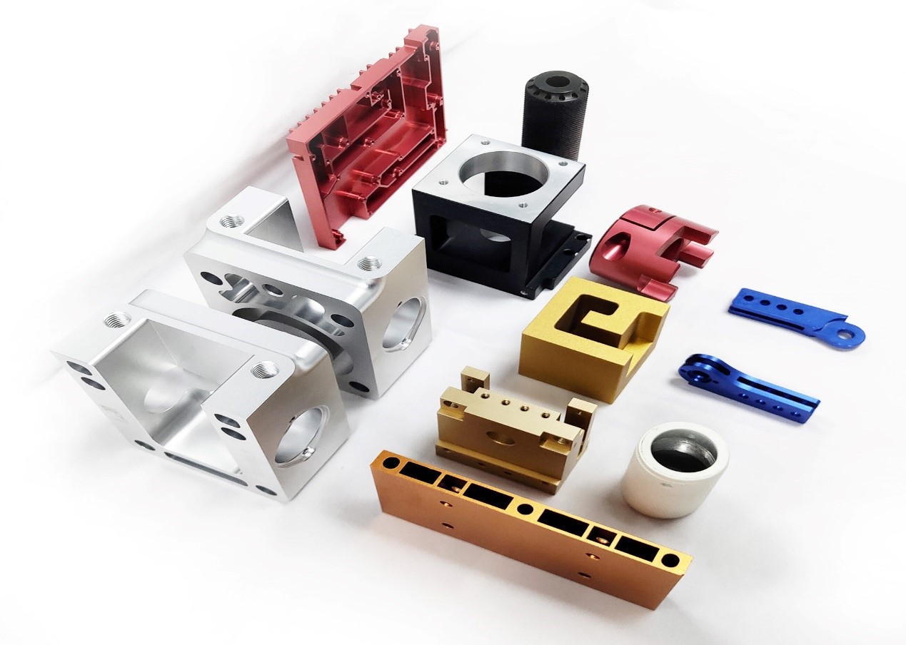
CNC Machining centers developed from CNC milling machines. The biggest difference compare to CNC milling machines is that the machining center has the ability to automatically exchange machining tools, by installing tools for different purposes on the tool magazine, the machining tools on the spindle can be changed through the automatic tool changing device in a single clamping device to achieve a variety of machining functions.
CNC Milling Finish
Process
Roughness Ra(um)
Cylindrical milling cutter milling (rough)
12.5~3.2
Cylindrical milling cutter (fine)
3.2~0.8
Cylindrical milling cutter (precision)
0.8~0.4
Cylindrical milling cutter (rough)
12.5~3.2
Cylindrical milling cutter milling (fine)
3.2~0.8
Cylindrical milling cutter milling (precision)
0.8~0.4
Cutter milling (fine)
12.5~3.2
End milling cutter (rough)
3.2~0.4
End milling cutter (precision)
0.8~0.2
High speed milling (rough)
1.6~0.8
High speed milling (fine)
0.4~0.2
CNC milling centers and high-Precision Machining centers. Ordinary machining center, resolution of 1μm, maximum feed speed of 15 ~ 25m / min, positioning accuracy of about 0μm. High-precision machining center, resolution of 0.1μm, maximum feed speed of 15 ~ 100m / min, positioning accuracy of about 2μm. Between 2 and 10 μm, with a ± 5 μm more, can be called precision grade. FCE equipped with different grade and different size CNC milling center. Take in to account into both economic and quality in parallel.
Post-processing is the final step in the CNC machining process. In a quick guide, we offer a lot of surface treatments to complete your final parts and get them to meet strict specific requirements. It should be noted that in CNC machining, post-processing is in optional, as the quality of the machined parts is already very high.
The anodizing process allows the part to obtain excellent corrosion resistance, increasing the hardness and wear resistance of the surface. Anodizing is also the most common pre-painting treatment, which can help the painted surface to obtain good adhesion. We typically apply two types of anodizing in our production: Type II, corrosion resistant; Type III is thicker, adding a layer of wear resistance. Both anodizing processes can achieve a variety of color effects.
Grinding polish, it offers the fastest turnaround parts and does not require post-processing. The surface finish of the grinding part is equivalent to 125 um in Ra, and the requirements can be increased to 63, 32 or 16 um Ra. Minor tool marks may still be visible on the last part.
Powder Coating is thermoplastic powder spraying directly on the processed part. The sprayed parts are then baked in an oven to form a durable, abrasion- and corrosion-resistant plastic coating. In the powder coating process, its color, brightness, surface roughness can be customized.
Shot peening is the high-speed spraying of beads of different hardnesses and sizes onto the surface of the part. To get different textures and brightness of the surface. Since the surface has been hit by similar forging beads, the hardness and wear resistance of the surface have also been enhanced.
CNC machining is a universal machining process, especially parts that can be cut and machined can be achieved through CNC, from simple shape shapes to complex curved structures. However, as with every manufacturing technique, CNC machining has some design limitations. We break them down as follows to ensure that your products are optimally designed to better fit the CNC machining process.
When designing parts, the size of each part is different according to the application environment, working conditions, etc., and the requirements for the machining accuracy of the workpiece are also different. Although CNC machining can achieve very high machining accuracy, we should also be aware that demanding machining accuracy and accuracy (strict product tolerances) usually mean Longer production times and higher costs. If a specific tolerance is not specified in the product design, we recommend choosing at the following levels.
Permissible deviations in mm for ranges in nominal lengths
Tolerance Class Designation(Description)
fine
medium
coarse
very coarse
0.5 up to 3
±0.05
±0.1
±0.2
--
over 3 up to 6
±0.05
±0.1
±0.3
±0.5
over 6 up to 30
±0.1
±0.2
±0.5
±1.0
over30up to 120
±0.15
±0.3
±0.8
±1.5
over120upto400
±0.2
±0.5
±1.2
±2.5
over 400up to 1000
±0.3
±0.8
±2.0
±4.0
over 1000up to 2000
±0.5
±1.2
±3.0
±6.0
over 2000 up to 4000
--
±2.0
±4.0
±8.0
The highest precision of our equipment is 0.001, and the recommended most precise machining requirements do not exceed +/-0.005mm
All internal vertical edges of our products need to have rounded corners instead of right angles. This is because the tools used in CNC milling are cylindrical, which means they cannot produce inner right-angled edges. The fillet required by this process is called the inner corner fillet. When designing parts, the larger the inner corner fillet, the more efficient the production process. Because of the larger fillets, larger diameter milling cutters can be used to increase milling speed, and fewer swaps can be made to improve accuracy.
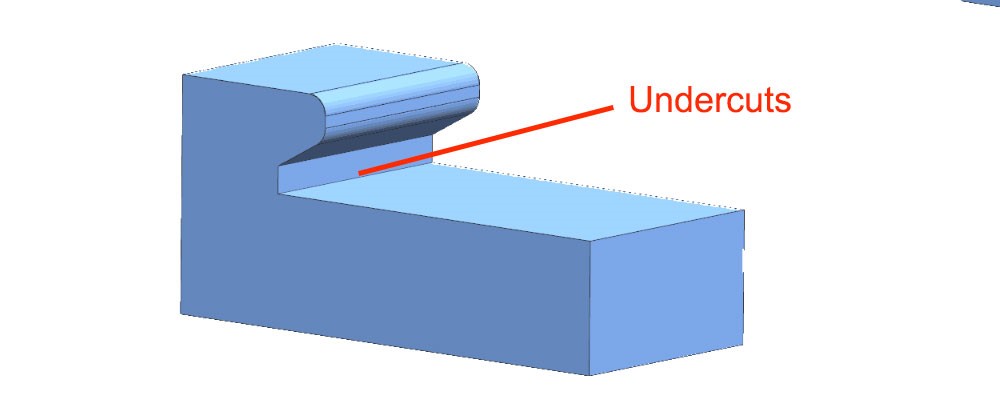
Undercut cannot be machined with standard milling cutters, so the use of retract slots for parts should be avoided when designing CNC machined parts. In particular, for non-standard inner contour shapes, customized machining tools are required, which will greatly increase processing time and costs. Secondly, if undercut can not be avoided, due to the limited length of cnc tools, the undercut can not be too deep. If they are too deep or the location is difficult to reach, they will not be able to be produced because the CNC tool cannot reach the machining location.
CNC machining requires your part design to meet minimum wall thickness requirements. In general, it is recommended to choose the thickest possible and avoid very thin or characteristic walls. This is because CNC tools processing thin-walled parts will cause vibration deformation, which may cause interruptions or damage, and the size is out of specification. The standard minimum wall thickness for CNC machined metals is 0.030" (0.76 mm) and for plastics is 0.060" (1.5 mm).
When designing parts, it is useful to choose the largest possible thread size because smaller taps have a higher risk of breaking during production. If possible, avoid using deep hole threads as they lead to higher production costs, especially when custom tools are required.
In principle, materials with high hardness are easier to process because better processing accuracy can be obtained, but they are limited by the hardness of processing tools, so the hardness of the generally recommended parts is 8 ~ 60HRC, and for metal materials, the hardness is greater than stainless steel Followed by cast iron, followed by copper, and finally aluminum, while the processing of ceramics, plastics, etc. belongs to the processing of non-metallic materials. Fast production time.
Although CNC can process thermoplastics, the material properties of polymers still have many difficulties for CNC processing. First, due to poor thermal conductivity, many thermoplastics melt or bend when in contact with CNC milling machines or drill bits. Secondly, the processing of plastics, because the hardness is low, the size accuracy caused by the knife during product clamping and processing is not high. For those parts that do not have special requirements for the strength and hardness of the metal, thermoplastics can provide a cheaper alternative.
Simplifying product design while taking into account functionality usually saves production time and reduces production costs. Because the manufacture of complex structures and surfaces often requires complex longer passes, more layering to obtain the same fine contour quality. This means higher production costs.
Using the same milling machine machining features, larger and same internal fillets, can reduce the number of tools used to reduce machining time. For example, if a workpiece needs a 10mm end face milling cutter to process some features, it also needs a spherical milling cutter to process a curved surface, and a 2mm milling cutter to process a fine groove, which will require repeated tool changes and reduce the machining efficiency
The choice of raw material for machining can have a significant impact on production time and costs for CNC machining. If possible, choose a material with good processability, such as brass or aluminum. For those applications that do not require metal hardness and strength, CNC machining of engineering plastics like PMMA and ABS also helps to reduce costs because the material blank is cheaper, and the processing efficiency is higher.
Higher tolerances and thinner wall thicknesses also increase THE CORRESPONDING CNC machining costs, as it takes time to achieve higher precision cutting. If your product or component can accept a larger size range, choose a lower tolerance to reduce production time and costs. The same is true for wall thickness: a larger wall thickness margin should be chosen.
Surface treatment is often the final stage of the CNC machining process, which can also affect the cost of your entire project. Choosing less surface treatment for your part or product can lead to better time and cost efficiency. FCE can recommend to you how to optimize the surface treatment to balance the conflict between cost and quality according to your final needs.
FCE facilities are equipped with the most advanced and highest precision 3, 4 and 5-axis CNC machines, which allows us to complete your order in record time
1. 15+ year work experience engineers
2. Fastest 5 days delivery
3. Prototypes can be machined as quickly as 1 day.
4. More than 200 metals and plastics material available in stock
5. Tolerances as low as +-0.005mm
6. ISO 9001: 2015 certified factory
7. 40+ CNC machines
8. 50,000+ machined parts per month
We cooperated with many world top 500 companies and awarded good responds always.
Cnc Milling,Cnc Milling Services,Custom Cnc Milling,Cnc Lathe And Milling Machining Suzhou FCE precision electronics Co., LTD , https://www.fukeyifcesz.com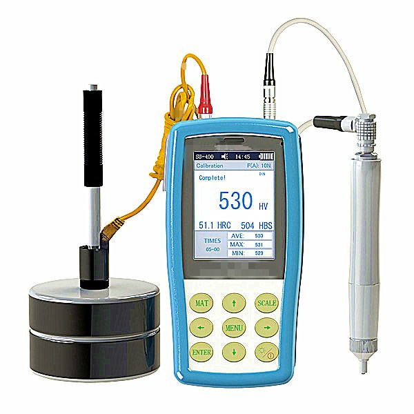
It is a combined portable hardness tester  which  integrated the ultrasonic hardness testing method and dynamic Leeb hardness testing. It supports not only the UCI measurement of ultrasonic including manual probe 1kg, 2kg, 5kg, 10kg and motorized probe 0.3kg, 1kg but also the seven dynamic  impact devices of Leeb measurement that is D, DC, DL, D+15, C, E, G to do rebound measurement.
SU-400 is an instrument with two applications. It can test thin, bright and clean specimen with the ultrasonic method and rough big specimens with Leeb rebound method. It solves the dilemma that Leeb method can not test  electroplated coatings and hard coatings and ultrasonic method can not test coarse-grained materials.
2.Features:
 2.1One instrument two applications-Support  ultrasonic probe and Leeb impact device.
 2.2Metal shell-Metallic texture, shield electromagnetic interference effectively, improve instrument stability.
 2.3Color screen display-Display the current measurement value, accumulative measurement value, Max, Min and Ave value.
 2.4Bluetooth transferring-Support wireless  Bluetooth  print and data transferring.
 2.5Mass storage-Save 1000 groups data.
 2.6Calibration access-Save 20 groups calibration data without doing calibration for the same material over and over.
3.Specifications:
Product nameÂ
Dynasonic Hardness TesterÂ
ModelÂ
YL-SU-400
Ultrasonic Probe
Standard delivery:2Kgf(optional Manual 1Kgf,5Kgf,10Kgf,motorized 0.3Kg and 1Kgf)
Impact Devices
Standard delivery:D(optional DC,DL,D+15,C, G)
Hardness Scale
HL, HV,HB,HRC,HRB,HRA,HS, etc.Â
Measuring Range
HV:50~1599;Â Â HRC:20~68;Â Â HB:76~650;
HRB:41~105;Â Â HLD:170~960
Measuring Accuracy
HV:±3%HV; HRC:±1.5HRC; HB:±3%HB;HL: ±8HL
Resolution
0.1HR, 1HV, 1HB, 1HLD,0.1HS
Result Display
Measurement value, Max, Min, Ave, single mode, batch mode, etc.
Data Storage
1000 group test results and 20 group calibration data
Data Transfer
Bluetooth
Continuous Working Period
10h (turn off the back light)
Operating Environment
Temperature: -10ºC~50ºC; Humidity: 30%~80%
Operating Voltage
4.2V
Charge Mode
USB
Dimension
160x80x31mm
WeightÂ
≤500g(probe not included)
4.Standard Delivery:
Product Name
Product Name
Product Name
Instrument Main Body
Rockwell Hardness Block
Accessories Box
2Kg Manual Probe HP-2K
Leeb Hardness Block
USB Cable
Impact Devices Type D
Probe Cable
Operation Manual
5.Optional Accessories:
Product Name
Product Name
1Kg Manual Probe HP-1K
Rockwell Hardness Block HRC
5Kg Manual Probe HP-5K
Vickers Hardness Block HV
10Kg Manual Probe HP-10K
Big Cylinder Support Ring
0.3 Kg Motorized Probe MP-300
Mini-Printer
1Kg Motorized Probe MP-1000
Testing Stand
Deep Hole Probe Cap
Handy Silicone Shell
Small Cylinder Support RingÂ
Plan Support Ring
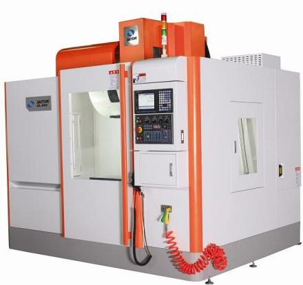
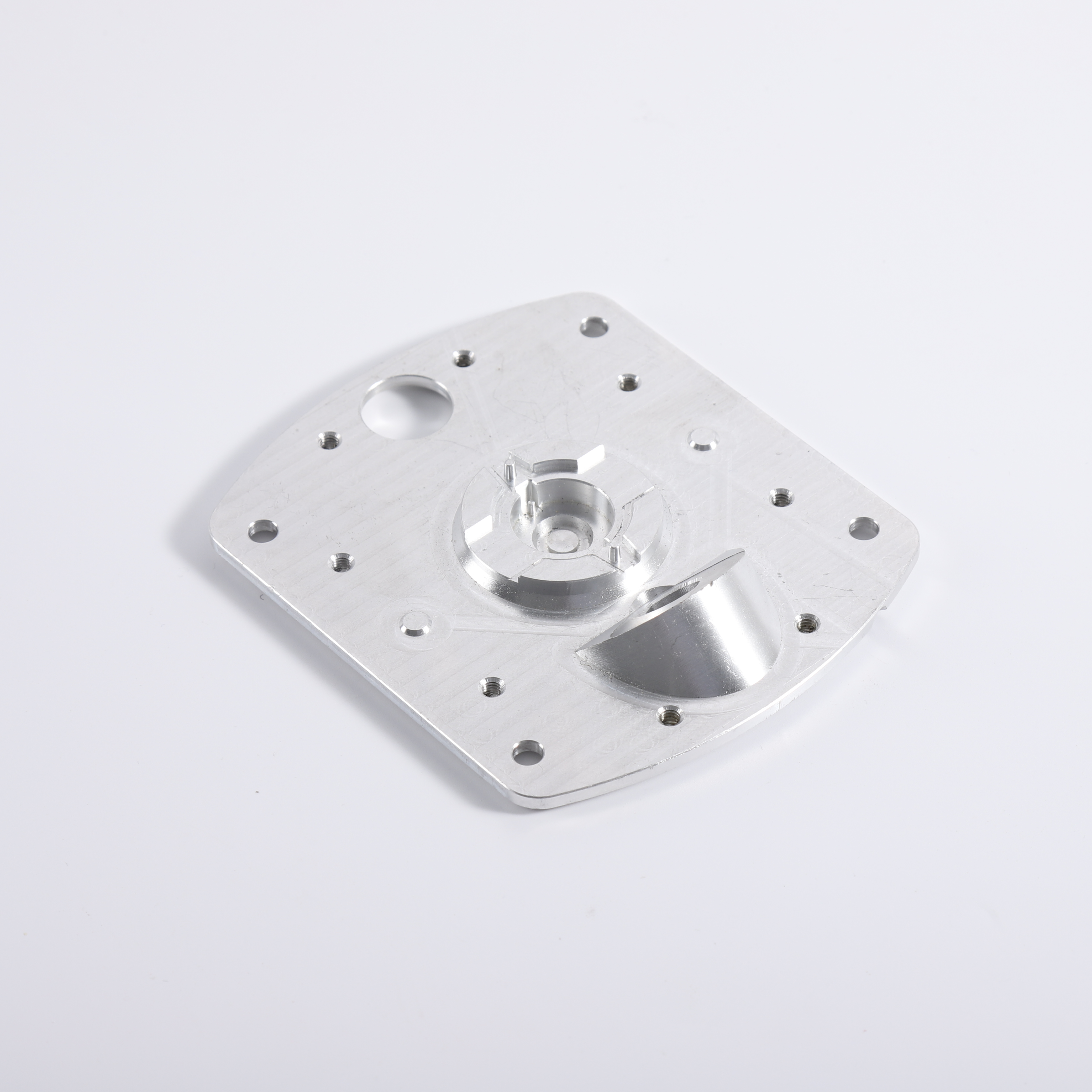
In general, computer numerical control milling machine (CNC) machining is a deductive manufacturing technique that programs 3-axis linkage, complex to 5-axis linkage, drives milling cutters to remove layers from solid blocks called blanks to produce finished parts. CNC milling is one of the main types of CNC Machining, which uses cutting tools that rotate at a speed of several thousand to tens of thousands of revolutions per minute (RPM) to precisely remove materials to obtain parts with complex surfaces. In addition to milling, CNC machining is also equipped with drills, boring tools, thread cutters and other tools to complete different part features at once. CNC machining produces parts based on a computer-aided design (CAD) model that is sent to a CNC machine through computer-aided manufacturing (CAM) software.
CNC milling accuracy
CNC Finishing surface treatment
Anodized
Polishing
Powder coatings
Shot blasting
Design of CNC machining
General Tolerance
Interior angle
Undercut
Chamber wall thickness
Thread
Metal
Polymer
Cost optimization of machined products
Simplify product design
Reduce cutter changes
Proper material selection
Tolerance and wall thickness
Choice of surface treatment
FCE Machining services
Model NO.: YL-SU-400
Calibrating Method: Standard Hardness Test Blocks
Rated Voltage: 220V
Support Language: English
Customized: Non-Customized
Hardness Scales: Hv, HRC, Hra, Hrb, Hb
LCD: Color Screen
Data Display: LCD Backlight, Adjustable
Language: Chinese, English, German, Portugese, Turkish
Print: Bluetooth
Packing Dimension: 320 X 430 X 155mm (L *W *H)
Net Weight: 500g
Word Input: Letters and Numerals
Packing Weight: 4.3kg
Data Output: RS232 Hyper Terminal/Bluetooth Printer
Trademark: Yuelian
Transport Package: Carton
Specification: 160*80*30mm
Origin: Dongguan China
HS Code: 9024102010
Lab Equipment Portable Universal Ultrasonic Hardness Tester (YL-SU-400)
Â